Having had limited success with my antenna building and trying to get a better signal in from the club repeater, I wondered several times today if it was feasable to assemble a low power cross-band repeater and put it in a location that I can reach on low power from my apartment, and from that same location also key and receive good signal from the repeater.
The aparment complex just put garage door openers in our garages, which meant they had to run power to all of them. Of course they only put in one outlet right where the opener is, but I think I can work around that.
So today I positioned my wife in front of my ICOM and told her what I was looking for, and then went out to the garage to do a test on 70 cm. With 3 watts to the back side of my 2 meter yagi-uda, full signal with full quieting. I ran a similar test from there to the club repeater with 5 watts on 2 meters. Also full quieting on receive.
So since this dovetails nicely with my desire to build a special events repeater, I think I'm going to order in a couple of the Baofeng UV-5R's ($30 each on Amazon) and use them as a base for the repeater. I have lots of features I want to include. Temperature sensing and fans to vent the housing to keep the radios at a suitable temperature. It should have the ability to turn the repeater function on and off remotely. The ability to play pre-recorded messages. The ability to identify itself either with CW or a different message. Extended battery life with low battery warning. The ability to program via computer, or in the absence of a computer to be set to some sort of default so it can be programmed remotely via DTMF. Some sort of solar battery charging system. It won't ever completely charge the battery, but it will help extend the battery life. The unit needs to be housed in some sort of weather resistant environment while still allowing for ventilation.
Step one will be to make the simple cross-band version. Once it's proven, I can go from there.
Enough musings for tonight. I'm net control for the new ham net, so I better be getting ready. It starts in 30 minutes!
73
Steve
KDØWSW
Sunday, December 29, 2013
Saturday, December 28, 2013
Headset with boom mike on the cheap
I spend at least a couple hours most Sunday evenings on the radio participating in a couple of local nets. And since my "shack" is the livingroom that I share with my lovely bride, I needed to find a way for us to be able to co-exist in that space at the same time without either of us driving the other crazy. So headphones were in order. I've actually got some very nice pairs of stereo headphones. But they kept getting tangled in the mic cord. So I decided I wanted a headset with an attached mic.
There are lots of very nice commercial communications headsets. But being on the limited budget that I am, I opted for a slightly different route. There are many very affordable gamers headsets for computers. And actually, the ones that have separate mic and headset connections are much less expesive than the USB variety. The ones with the mic/headset connectors are the ones we want. The thing about computer headsets is that they almost all expect the mic connection to be powered since they use an electret-condenser type mic element.
If your radio uses a similar type of microphone, then this style of headset will work for you as well. What you will need is a resistor and a capacitor. In the mic connector, you'll likely find some sort of power avaialble. In my ICOM, it as +8vdc. You wire the resistor from the positive voltage to the tip of the microphone, and then the capacitor from the tip to the mic input on the radio. You'll also need some sort of PTT switch.
In my case, I had the wiring harness from an extremely old Telex headset that I owned back in the 70's. The headset is long gone, but the harness has a very nice PTT switch assembly. So I scavenged that from my junk box and started wiring. Here's pictures of the results.

 What you see: An inexpensive Turtle Beach gamers headset and the harness I use to hook it up to my radio. The harness consists of an 8 pin microphone connector, and from that is a wire that is long enough to reach around the back of the radio and plug into the external speaker jack. The oddly shapped thing close to the other end of the cable is the PTT switch. From that is 2 3.5mm trs inline jacks. One for the mic, one for the headset. Since all mic connector wiring is different, you would need to look up the wiring diagram for your specific radio. But the addition of the resistor and capacitor makes the whole thing work like a champ. I get great signal reports whenever I use it.
That's enough for today.
73
Steve
KDØWSW
There are lots of very nice commercial communications headsets. But being on the limited budget that I am, I opted for a slightly different route. There are many very affordable gamers headsets for computers. And actually, the ones that have separate mic and headset connections are much less expesive than the USB variety. The ones with the mic/headset connectors are the ones we want. The thing about computer headsets is that they almost all expect the mic connection to be powered since they use an electret-condenser type mic element.
If your radio uses a similar type of microphone, then this style of headset will work for you as well. What you will need is a resistor and a capacitor. In the mic connector, you'll likely find some sort of power avaialble. In my ICOM, it as +8vdc. You wire the resistor from the positive voltage to the tip of the microphone, and then the capacitor from the tip to the mic input on the radio. You'll also need some sort of PTT switch.
In my case, I had the wiring harness from an extremely old Telex headset that I owned back in the 70's. The headset is long gone, but the harness has a very nice PTT switch assembly. So I scavenged that from my junk box and started wiring. Here's pictures of the results.


That's enough for today.
73
Steve
KDØWSW
Back to the drawing board
I think maybe the reports of my antenna success were a little premature. I dug out my icom mobile/base today and tried out the loop. It works, but not as well as I thought. With my yagi-uda correctly positioned in my apartment, I get an S9 from the repeater. With the loop, I was getting just under S3. While that's not bad for a first attempt at my own design, it's not something I can use on a daily basis. I might take it down to the office and see what it does from there.
Ah well. If I didn't experiment, I wouldn't learn anything.
73
Steve
KDØWSW
Ah well. If I didn't experiment, I wouldn't learn anything.
73
Steve
KDØWSW
Thursday, December 26, 2013
Yet another antenna
In my ever continuing quest to get a signal out of my apartment, I came up with another idea. Rather than a magnetic loop for 2 meters, how about a directly driven full wave loop? Where on earth did that come from?
For a year or year and a half now, I've been experimenting with TV antennas. The area we live in still has 2 channels on VHF-HI (7 and 9). And if you live in a garden level apartment like I do, pulling them in is next to impossible. I was perusing the net one Saturday afternoon, and found the website digitalhome.ca. On there, there is a section dedicated to experimental antennas. After reading for quite some time, I decided to make a loop antenna without a reflector. Something that could be hung in a window or door. The loop in question is 23 1/2 inches in diameter, 80+ inches long. And if you work that out, that fits the 2 meter band fairly well. The loop itself is made from 1/4 copper tubing purchased from a local home improvement store. And after having made a couple of them, I actually cut a form out of particle board. Makes it much easier to take the cut piece of copper and form it into a circle.
I already had one that I'd made up a few months back to experiment with, so I grabbed it and removed the 300-75 ohm balun that was on it. I decided to make a half-wave match as depicted on this website http://www.buxcomm.com/antennas.htm, made out of rg-58 coax that I had on hand.
The results were very satisfactory. I'll have to hook it up to my Icom radio to actually check the signal, but I tested using my HT, and was able to hit the repeater. The receive sounded as good as when I use my yagi-uda antenna. Hopefully, I'll be able to hang this one from the curtain rod in the livingroom, position it for best signal, and then leave it up. Once I get it finalized, I'll take a couple pictures and put them in this post.
And of course it's well past my bedtime, and I have to go to work tomorrow. So until next time:
73
Steve
KDØWSW
Wednesday, December 25, 2013
Sleep is not an option
It's very early in the morning on December 25th. I've already been up for a couple of hours. And no, I'm not up in anticipation of Christmas morning. The last few mornings I've been up in the middle of the night thinking about projects. Seems I do my best thinking when I'm asleep.
What's on my mind? Several things really.
I mentioned in my first post that I live in an apartment complex that doesn't permit outdoor antennas of any kind. Television, or otherwise. I live on the ground floor of my building, which except for my apartment is at least 4 feet below grade. The building itself rather than being a normal stick-built unit, is constructed of structural concrete panels for the outside walls and the ceiling, and covered with a very nice brick fascade. So getting a signal out of here is a challenge. My apartment has one south-southwest facing sliding door and window, and one west-southwest facing window. The building itself is surrounded on 3 sides by other very close by structures two of which are the same construction as this building. The challenge? The repeater for the local club (WØGQ) is in the opposite direction from my apartment.
I've tried various antennas and locations in my apartment. I've tried a roll-up j-pole taped to the fixed part of the sliding glass door. I've tried the mag-mount vertical that I use on my car sitting outside on my barbecue grill (in the dark of course). And I built a 3 element yagi-uda based on an Instructable that I found. It's composed of sections of 1 inch wide measuring tape and 1/2 inch PVC pipe and fittings. This last one seems to work the best. It's the location for best signal that's the issue. Rather than up next to a window, the antenna has to sit in between my livingroom and kitchen and pointed roughly 180 degrees from the repeater. Why is this a problem? Well, putting it up and taking it down when I'd like to have the radio on is, in a word, inconvenient. If it was just me, I'd probably leave it up. But I do share my space with my wife. And while she is very kind and tolerates a lot from me, I sincerely doubt that she'd consent to having this "work of art" in that spot all the time.
So what I'd like to do is get a run of coax out of here somehow and either put up some sort of stealth antenna with a better line of sight to the repeater, or maybe even up three floors into the attic space so I could put a small omni up there. I know there are ways to go out through windows and possibly doors without drilling. The only place that would be viable is the sliding glass door since the lower half of the part that opens does sit below grade and is mostly protected from view.
Why is any of this important? For one thing, I'd like to set up a dedicated echolink system so I can monitor the repeater while I'm at work. I'm allowed to listen to whatever I want while I'm working as long as I keep the volume down and don't put on headphones. Reception in the building I work in is poor, so echolink seems like the solution. I could set the radio up here, and link in from my computer at work. Then the radio traffic would be mixed in with the music I regularly stream.
Which brings us to why I'm up in the middle of the night. Echolink. It would be nice to be able to purchase a unit to do the linking. But alas there's that limited budget thing again. So being in DIY mode, I found a nice schematic for something that will let me build an echolink interface that will double as a packet radio interface when it's coupled with a computer and sound card. Computers I've got. Parts for the build will be a minor challenge. I'll need to scavenge the larger ones off some old computer motherboards and cards. Specifically I need relay(s), 600 ohm isolation transformers, and 3.5 mm jacks, and at least one board mount RJ-45 jack. Fortunately, after scrounging through my computer junk pile, I came up with boards that have all those parts on them. The rest that I need I can come up with from my parts kit (something I put together long ago for another project), or was able to pick up a the local electronics shop yesterday. But of course, it's the middle of the night. And my lovely wife is sound asleep. So firing up the heatgun to depopulate those computer boards is not an option.
I have several projects in mind that I'd like to tackle. The echolink interface with a dedicated radio. A portable, self-contained event/emergency low power repeater. An APRS setup for my car. And some additional antenna experimentation.
Time to make some breakfast.
73
Steve
KDØWSW
Tuesday, December 24, 2013
No! Wait! Cut the GREEN wire!
So, you need to power your radio...
That was my problem. I had radios, but nothing to power them with in the house. So I went into scrounge mode.
When it comes to computers and electronics, I tend to save things. Probably longer than I should. But you never know when you're going to need something.
I looked online, and found the purpose-built radio power supplies to be out of my price range. But as it turned out, I had several "used" computer power supplies at my disposal. Now they are definitely *not* purpose-built for ham radio. And rather than just one voltage, they output several voltages at various amperages depending on the wattage of the power supply. Current available for each voltage is usually listed on a label attached to the unit. Those voltages are +12 -12 +5 and +3.3. I was only interested in the +12. Of course ideally I'd want something that output 13.8, but most radios are tolerant enough to accept 12 volts.
Computer power supplies have a *bunch* of multi-colored wires coming out of them. That in itself can be a show stopper for some folks. Plus all modern computer power supplies have a *feature* that makes them pretty much unusable for the average consumer. There's no on-off switch. Or if there is, it doesn't seem to do anything when it's removed from the computer case.
The feature in question is that the computer motherboard controls the on-off function. So when you tell your computer to shut down, as a final act, the motherboard tells the power supply to go into a suspend mode. It doesn't actually turn off, but it does draw very little power.
So what to do? Well, first have a look at the connector of a computer power supply:
 Looks like a mess doesn't it? If you look at one of these closely, you'll find that among all the wires, very few wires have colors that aren't repeated. To be specific: Brown, Blue, Green, White, Violet, and Gray. All of the other wires are either Black, Red, Yellow, or Orange. So? Well one of those wires is responsible for turning the power supply on and off. Interested? I was. Turns out it's the green wire. If you connect the green wire to one of the black wires (ground), as long as the power supply is plugged into mains power, it will magically turn on.
So now what? There are two choices. If you are planning on dedicating this power supply to something other than computer use, then I would recommend removing all the extra wires and putting in something that will handle the current of the project you are working on. In my case, I opened up the unit and removed all but one red, yellow, orange, and black. Of course I left the green and an additional black to provide the on-off function. In addition, I had some very flexible 8 gauge wire that is generally used in sub-woofer amplifier installations. So I attached that to 12 volts and ground. Buttoned everything up, and viola! A re-purposed power supply. Here is a picture of my re-purposed supply:

In the foreground you can see the rocker switch attached to the green and black wires. Since I use this power supply for experimentation as well as powering my radios, you can see banana plugs on a couple of the wires. The large red and black wire connect inside as described above and terminate in a Deans power connector. Those of you that are involved with electric radio controlled models will recognize the connectors. I probably should have used the Anderson Power Pole connectors, but I didn't have any of those and I *did* have the Deans connectors. I can always make an adapter later.
The other choice is to take the connector that mates with this one off a dead computer motherboard and make your connections there. I did that for a smaller unit I had that I didn't want to carve up. The subject of removing parts from printed circuit boards is covered in detail in other places on the web. I used the hot air method. Provided by a scrapbooker's embossing tool of all things. Think of it as a baby paint stripping heat gun.
Don't have any spare supplies lying around and still trying to save a buck? Look on E-bay, Amazon, Tiger Direct, Newegg, the possibilities are endless. I've actually purchased them from Newegg for as little as 12.95 with free shipping.
Well, that's enough for today. Who knows what tomorrow will bring?
73
Steve
KDØWSW
That was my problem. I had radios, but nothing to power them with in the house. So I went into scrounge mode.
When it comes to computers and electronics, I tend to save things. Probably longer than I should. But you never know when you're going to need something.
I looked online, and found the purpose-built radio power supplies to be out of my price range. But as it turned out, I had several "used" computer power supplies at my disposal. Now they are definitely *not* purpose-built for ham radio. And rather than just one voltage, they output several voltages at various amperages depending on the wattage of the power supply. Current available for each voltage is usually listed on a label attached to the unit. Those voltages are +12 -12 +5 and +3.3. I was only interested in the +12. Of course ideally I'd want something that output 13.8, but most radios are tolerant enough to accept 12 volts.
Computer power supplies have a *bunch* of multi-colored wires coming out of them. That in itself can be a show stopper for some folks. Plus all modern computer power supplies have a *feature* that makes them pretty much unusable for the average consumer. There's no on-off switch. Or if there is, it doesn't seem to do anything when it's removed from the computer case.
The feature in question is that the computer motherboard controls the on-off function. So when you tell your computer to shut down, as a final act, the motherboard tells the power supply to go into a suspend mode. It doesn't actually turn off, but it does draw very little power.
So what to do? Well, first have a look at the connector of a computer power supply:

*** I'm inserting the usual disclaimer here. Working on power supplies is potentially life threatening. Make absolutely certain you have removed the connection from the mains, and done your best to drain the unit of any residual power. The capacitors inside these units can keep their charge for months. Use extreme caution. Additionally, if you choose to purchase one of these to modify, opening the case or cutting any of the wires *will* void your warranty. Please consider all this information carefully before you proceed. End of disclaimer ***

In the foreground you can see the rocker switch attached to the green and black wires. Since I use this power supply for experimentation as well as powering my radios, you can see banana plugs on a couple of the wires. The large red and black wire connect inside as described above and terminate in a Deans power connector. Those of you that are involved with electric radio controlled models will recognize the connectors. I probably should have used the Anderson Power Pole connectors, but I didn't have any of those and I *did* have the Deans connectors. I can always make an adapter later.
The other choice is to take the connector that mates with this one off a dead computer motherboard and make your connections there. I did that for a smaller unit I had that I didn't want to carve up. The subject of removing parts from printed circuit boards is covered in detail in other places on the web. I used the hot air method. Provided by a scrapbooker's embossing tool of all things. Think of it as a baby paint stripping heat gun.
Don't have any spare supplies lying around and still trying to save a buck? Look on E-bay, Amazon, Tiger Direct, Newegg, the possibilities are endless. I've actually purchased them from Newegg for as little as 12.95 with free shipping.
Well, that's enough for today. Who knows what tomorrow will bring?
73
Steve
KDØWSW
Sunday, December 22, 2013
ICOM IC-3220H Technician Special
In November of 2013, I attended my very first hamfest in
Davenport Iowa. I wasn’t sure what to
expect. It was fun to walk through and
see all the things available. And I
managed to pick up a couple adapters so I could use some additional antennas
with my HT. But one thing caught my eye
as I was walking through. That was what
looked like a well-used ICOM IC-3220H dual band radio. I was looking for something I could use as a
base and possibly as an APRS unit. The
radio had a note on it that said it had intermittent transmit and that it would
be an easy fix.


At that point I guess I should have listened to the little
voice in my head that was saying, “Warning!, Warning!, Danger Will Robinson,
Danger!”.
Against my better judgment, I bought the radio. I figured if nothing else, it would be a good
learning experience. When I bought it,
the man I bought it from told me the previous owner had replaced the finals but
was experiencing this intermittent transmit.
Step 1: Build a dummy
load. I needed something I could sink
the transmitter with. I’m cheap at
heart, and I couldn’t see spending an arm and a leg on one. So I resorted to my old standby, Google. Many thanks to all the Hams, that whether they
know it or not have been my Elmers in this situation. I found two different ones that caught my
eye. One that used 4 - 100 ohm, 100 watt
thick film resistors mounted on a heat sink,
and one that used 20 – 1k ohm, 3 watt resistors. Both were built into quart paint cans and
filled with mineral oil to help dissipate the heat. I settled on a hybrid design based on the one
by K4EAA. My design was a single 50 ohm,
100 watt thick film resistor mounted on a heat sink. The part I borrowed from K4EAA was the RF
detector that lets you measure output power using a simple volt meter. I bought all the parts from Mouser since I
don’t have much of a junk box yet. I could have gotten the thick film resistor
for a couple bucks less at Digi-Key, but by the time I paid for the additional
shipping, Mouser was the better deal. I
bought the paint can and miscellaneous nuts and bolts locally. A note about the mineral oil. Mineral oil is used both as a sealer for
butcher block countertops, and medicinally as a laxative. Both are the same. The slightly less than a pint bottle at a
home improvement store (I tried all three in my area) was between nine and
twelve dollars. I stopped at a local
hardware store, and they carried a full pint bottle, but only had one, and it
was just under four dollars. Pressing
on, I stopped at Wal Mart, and in the pharmacy section, I found the mineral oil
for a dollar and sixty nine cents per bottle.
The lesson learned, “Don’t dismiss Wal Mart as a source of parts for ham
radio.” And although I have the oil, I
have not put it in the dummy load yet. I
have the resistor mounted on a computer CPU heat sink. And none of my radios even come close to
being 100 or more watts. So for now I’ve
left it dry. When building your dummy
load, make sure you don’t use binding posts that can accidently short out on
the lid of the can. I spent almost two
weeks chasing gremlins because of that.
The magic formula for using a DVM to calculate a radio’s
power output:
((volts/1.414)squared)/50
Using my cheap DVM’s (I have two of them), I got similar readings
and within the correct amount for the radios I measured.
Step 2: Build an RF
probe. Using the same diode/capacitor
technique from the dummy load, you can build a simple probe. It’s helpful to be able to trace RF through
the circuit to see where it’s being lost.
Step 3: Schematics.
You *need* them. If you can find
a service manual for your radio, get it.
It will have much more than just the schematic. It will help you understand the various
components and their functions in your radio.
You may be very knowledgeable in radio repair and may not need this
item. If that’s the case, more power to
you. Me?
I’m a firm believer in reading and understanding manuals. In this case, I read the text description of
the various parts of the radio several times to get a flow for how things
worked so I could eliminate areas that I didn’t need to work on. I was very fortunate to find a copy of the
service manual for my radio on the web. Again,
Google is your friend. Expect the older
manuals to have been scanned rather than electronically produced. They may not be the best scans in the
world. In my case I had to look at three
different copies before I found one legible enough to use. It’s still not great when it comes to
voltages and things, but it’s still very helpful.
Step 4: Soldering
skills. Again, you *need* them. If you are unsure of your skill set, find
something else to practice on. When
working on high wattage RF, you want to make sure that you are leaving nice
rounded solder joints. Don’t believe
me? Have a look inside your radio at the
RF output section. Leaving pointed areas
of solder or parts leads provides the opportunity for arcing. That’s bad.
Step 5: A good work
area. I live in a small apartment with
my wife. And I don’t have the luxury of
my own work bench. So I usually take the
kitchen table hostage for my projects.
Thankfully my wife has come to accept this idiosyncrasy of mine. You will also want plenty of light. My wife scrapbooks, and has something called
an OTT light. It’s supposed to be a full
spectrum fluorescent. I usually borrow
that from her along with a magnifying lens on a flexible arm.
So now we’re at the point where I’m finally ready to get
started. Are you ready? A word of warning here. If your radio is still under warranty, any
work you do on it will undoubtedly void any you may have left. I am not responsible for your voided
warranty. So think about it before you
turn the first screw. Please? Carefully disassemble your radio. I generally have several sandwich bags around
that I can put groups of parts in that belong together. If it’s likely I’ll forget what the parts are
for, I’ll write on the bag with a sharpie so I can remember later where they
go. In my case, I took off the top and
bottom off the radio, and I took the shields on the RF sections off the
unit. It was immediately clear that the
PA (power amplifier) module on the VHF side of the radio had been replaced but
I wasn’t sure about the UHF side. How
could I tell? Well, without bashing the
last person to have worked on the radio, it was fairly obvious that the tech
had some trouble soldering the module into place. So I started on the VHF side, even though
neither side would transmit. I had
expected the issue to be common to both sides, but it turns out it was
not. After some false starts and some
retracing of steps, I came to the conclusion that the problem was the PA
module. I could prove that the required
400mw signal was reaching the PA module, and I could prove that the switching transistor
was applying the correct voltage to the PA module for the requested power
output, and I could prove that the PA module was receiving a full 13.8 volts
from the radio’s power bus. But when
keying the radio, no power was coming out of the module. So I carefully unsoldered the module. And once I did, three of the four leads from
the module fell out. Oops! That’s a problem. Unsoldering the module could have caused
that. I spent part of an evening looking
for a replacement module online. They seem
to be available, but no one posts prices except one place. And I’m not about to pay more for the module
than I did the radio. So with leads
falling out, my curiosity was piqued. I
felt like I really didn’t have anything to lose, so I decided to take the
module apart. The module had something
white oozing out all of the lead holes and around the sides of the case. I thought it might be potting compound. It turned out to be silicone sealer. I used my Xacto knife to break the silicone
seal and then gingerly pried the cover off.
Here’s what I found:

If you look across the bottom, you can see the pads where
the leads that are missing belong. One
lead is still attached. But take a close
look at the pad on the left. See how
black it is? When I looked at the bottom
of the lead that came from that position, it looked the same way. What does that tell you? Arcing!
That particular lead is the output of the module. At full power, the radio puts out 43 watts. That's about 70 volts peak to peak. So there is plenty of potential for sparking
if there is a bad or loose connection.
Of course at this point, I can’t tell if the module was defective, or
the issue was caused by the previous tech’s soldering problems. So it’s no wonder the radio had intermittent
transmit. I made the decision to try and
repair the module. Again, what could it
hurt? I already have a module that’s not
working. What’s the worst that could
happen? The module still wouldn’t
work? It was worth the risk in my
book. So I cleaned up the excess
silicone, and I cleaned the soot off the pad and the lead. Turns out the arcing pretty well destroyed
the pad. So I ended up soldering the
lead to the end of the part next to the pad.
I reattached the other two remaining leads. Then I got out my computer heat sink compound
and spread it on the back of the module.
Placed the module back in the radio, and soldered it into place. Here’s a picture of the module back in place
with the cover still off:

The results? Believe
it or not, it works! Full power into the
dummy load as measured by my DVM and the magic formula. At this point, I hadn’t tried it on the air
yet because I had the mic disassembled at that moment. And yes, I know I harped on soldering skills
early on. The soldering of the leads onto
the module itself was tough. I had to
use a high watt soldering iron because of the heat sink. But the places where the leads are attached
to the main board are nice and round.
Testing on the UHF side indicated the same problem. Good signal into the module, nothing coming
out. And the switching transistor is
turning the voltage to lead 2 on and off like it’s supposed to. This time I took a picture before I removed
the module.

It looks to me like this module has been replaced too. My reasoning behind that is that although
it’s hard to see here, there was some solder flux around the pads, and the
solder joints weren’t what I would call factory smooth. I’m not sure if it was done by the same
tech. The solder joints on this one are
much better than on the VHF side. Again,
this is a nothing to lose situation. It
already doesn’t work, so it’s not going to hurt for me to take it out, open it
up, and have a look. Here is what I
found:

Pin 2 (second pad from the left) was not connected. Pin 2 is what keys the module and causes it
to amplify the input signal. So in this
case the module was never getting turned on.
I didn’t see any evidence of arcing, so I have to wonder if this was caused
during installation. Opening this module
up was much more difficult than its VHF counterpart. There was considerably more silicone
used. I actually broke a tab off the
cover that goes between pins 4 and 5. If
I decide to put the cover back on, I’ll super glue the tab on before I
reassemble things. But at this point I’m
seriously considering leaving the cover off both sides. I don’t see that it serves any major purpose. Here is the module reinstalled after the
repair, again with the cover off:

The first test didn’t go so well. Power in, nothing out. But as I was probing around, something
changed. I took RF measurements again,
and this time I was getting unbelievable values. I suspect it was my homebrew RF detector
circuit. But I was getting output!
Lessons learned:
- Most importantly, listen
to the little voice in your head.
If it tells you to run, then run.
- If you are bound and
determined to take on a radio as a project, be prepared to improvise and
use some unorthodox methods.
Especially if your project radio is 20+ years old. Some of the major parts may not be available.
- If you can prove to yourself that something like a module is the culprit for your problem, don’t be afraid to disassemble and explore. This is ham radio after all. We are *supposed* to be able to homebrew solutions for our problems. Disassembling and exploring may provide you with a ready solution like it did for me. But if not, nothing ventured, nothing gained and you may learn a thing or two in the process.
I reassembled the radio enough to
test it on the air. Got a great signal
report and the unit behaved well. So it
was money and time well invested. I
still have one thing left to do, and that’s to replace the display lamps. They are both burned out.
To replace the display lamps, I decided to use high brightness white LED's rather than putting in OEM lamps. My reasoning was that the LED's should last longer. Probably longer than the radio does, and I only wanted to do this once. The original lamps were what I would call 12 volt grain-of-wheat bulbs. Something I would have used in model railroading in the 1960's.
The hole for the lamps is about 3 mm in diameter. And of course locally, I can only get standard T 1 3/4 size LED's which are 5 mm. I also wated something that was more of a flood light than a spot light. The LED's I had access to were water clear, so they fell into the spot light category. I could have ordered in some 3 mm LED's that were brighter than the ones I used, but being the impatient sort I decided to have a go with the 5 mm ones. If you choose to do this, be sure to buy spare LED's you *will* ruin some in the process.
I had read somewhere that you could diffuse the light from an LED by sanding it with a low grit sandpaper. So i dug out my Dremel tool, stuck one of the large grit sanding drums on it, turned it down to the lowest speed, and tried roughing up an LED. Lightly at first. That worked pretty well. So I sped the Dremel up and tried "resizing" the LED. I needed 2. I ruined 2. You have to be very careful no to open the "envelope" that contains the diode itself. I don't know what happens, but it gets very dim. I used the grind and fit method to try and avoid ruining any more of them. I finally got LED's fitted into both places and turned the correct direction to connect to the positive and ground pads. Of course the LED is a much lower voltage device than the lamps, so after doing some calculations, determined that I needed to include a 400 ohm series resistor. No such animal at my local Radio Shack, so I took the 470. Here's a picture of the result:

The lamp brightness setting in the menu works. But there's no difference between settings 1 and 2. Honestly, I'm thrilled.
I spent $65 for the radio. Probably more than I should have under the circumstances. And I spent almost two months rehabing the unit. Other than my labor, the only real cost I have involved was a plastic lens restoring kit to take a scratch out of the display, and $5 worth of parts to replace the lamps. But I ended up with a nice little unit that functions well as a base, and that I can use to experiment with without worrying about destroying any of my other equipment.
*** UPDATE ***
I recently had the oportunity to do some computer work for a gentleman that owns a business radio repair service. I detailed my process in this repair to him, and he told me that this issue is not all that uncommon. And it's not limited to ICOM. He told me they've seen this a number of times on several radios that used manufactured PA sections. It seems the issue started when the industry started using lead-free solder. Sometimes the joints don't hold. His suggestion was exactly what my solution was. Disassemble the module, resolder the leads, and put the module back in. He said he actually talked to a factory rep who while not directly encouraging the use of lead-based solder in doing the repairs, said that there was certainly nothing wrong with it when used in small amounts and with adequate ventialtion.
73
Steve
KDØWSW
Steve
KDØWSW
The Beginning
On a whim, on the 17th of September 2013, I decided to start my journey to become a licensed amateur radio operator.
I have always had the desire to get my license, but was never able to learn morse code. It might be different this time around, but since code is no longer a requirement, I decied to give it a try. The first available testing date in my area was going to be on the 21st of September. I've had a fairly good grasp of electronics, so all that was needed was to become familiar with the rules of amateur radio. Rather than getting any sort of study guide, I started taking tests online to see how I would do. I found out by taking the tests repeatedly, my scores got consistently better. So between the 17th and the 21st I took the test many times. And on the 21st, I went to Ames to take the test. I passed the Technician, but not the General. I hadn't studied for the General, so that really wasn't a surprise. What was a surprise was that I only missed it by one question.
So using the same techniques, I studied for and passed the General portion of the exam 5 days later.
On the 27th of September 2013, I was granted a Technician class license by the FCC to operate radios on those portions of the radio spectrum permitted by that class. Unfortunately, due to the government shutdown, I didn't actually receive my General class ticket until the 18th of October.
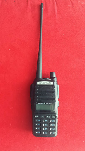
To get my feet wet, I purchased a Baofeng UV-82 HT online. This is in the same family as the UV-5R HT's. I picked this one because it had slightly higher output, a larger battery, and was just generally larger and easier for me to handle. This radio is definitely not in the same class as the Yeasu's, Icoms, and all the other fine equipment out there. But as a starter radio, as long as you go into it with your eyes open, I was quite pleased. Using an external antenna, I'm able to hit the local repeaters from my apartment on only 5 watts. Which is a major feat in itself due to my location. If you choose to go the Baofeng route, the best thing you can do is to get the programming cable and use a computer and CHIRP to set up your radio. I was never able to get the actual Baofeng software to work. CHIRP worked well.

Not long after, I picked up an Alinco DR-635T. I realized I needed a true mobile radio for my car. Again, this is not in the same class as the high-end radios, but I've not had any trouble with it. This is a dual band 2 meter/70 centimeter unit that will receive the full VHF HI/UHF spectrum plus Airband. One nice feature is that you can remove the face from the radio and put the chasis in a remote location. There is a "kit" for this, but I took the diy approach. Turns out that you can make your own extension cable from some inexpensive silver 6 wire phone cord and a couple ends. I also made a mount for the head from some black 1/4 inch PVC sheeting I have. Threw in a couple external speakers, and came up with an acceptable way to have the radio in the car without having to drill or cut to mount it. The added benefit is that I can pull the head and chasis from the car, reassemble it, and use it as a base unit. I can recommend the RT Systems programming software and cable for this radio. Makes setting it up a simple operation. I can also recommend RT Systems for their tech support. The first cable I received turned out to be bad. Together we were able to diagnose it in short order and they sent out a replacement overnight at no cost to me.
I'd like to get into HF. But I have what you'd call a very limited budget. That combined with living in an apartment complex that does not permit external antennas presents unique challenges. I do have my eye on the Peaberry V2 kit sdr radio. I have plenty of computers around to use it with, and with the addition of a kit based linear amplifier, I think it might be a respectable way to start.
I've always enjoyed tinkering with electronics, so I think this hobby will provide a great outlet for that. To that end, I've already done a couple projects. But those will be subjects of other entries.
73
Steve
KDØWSW
Subscribe to:
Comments (Atom)